NEO Planner V5.0 - CCD / CMOS Parameters - Explanations
Within the picture, click on the zone that you want to be explained: (not in all browsers available)
These settings are the fifth and last step in getting NEO Planner up and running.
Finally you define
some CCD / CMOS parameters for the planning process.
These parameters affect your CCD or CMOS camera and the behavior of your mount.
They are primarily required to calculate the exposure times, the number of
exposures and the timing during the night of observation.
Correct entry of these parameters is crucial for the usability of the planning
results.
In addition, some
parameters for the �Execute Search� function are used to detect new objects,
as well as to display the path of the planned objects against the star and
deepsky background.
Plausibility checks or actions are usually only carried out after leaving the cursor in the input field.
The
Astrometrica program
mentioned in the description was written by Herbert Raab from Austria.
At this
point, too, my sincere thanks for the opportunity to use his program in the past!
Tycho Tracker by
Daniel Parrott
is now the state-of-the-art program for astrometricians.
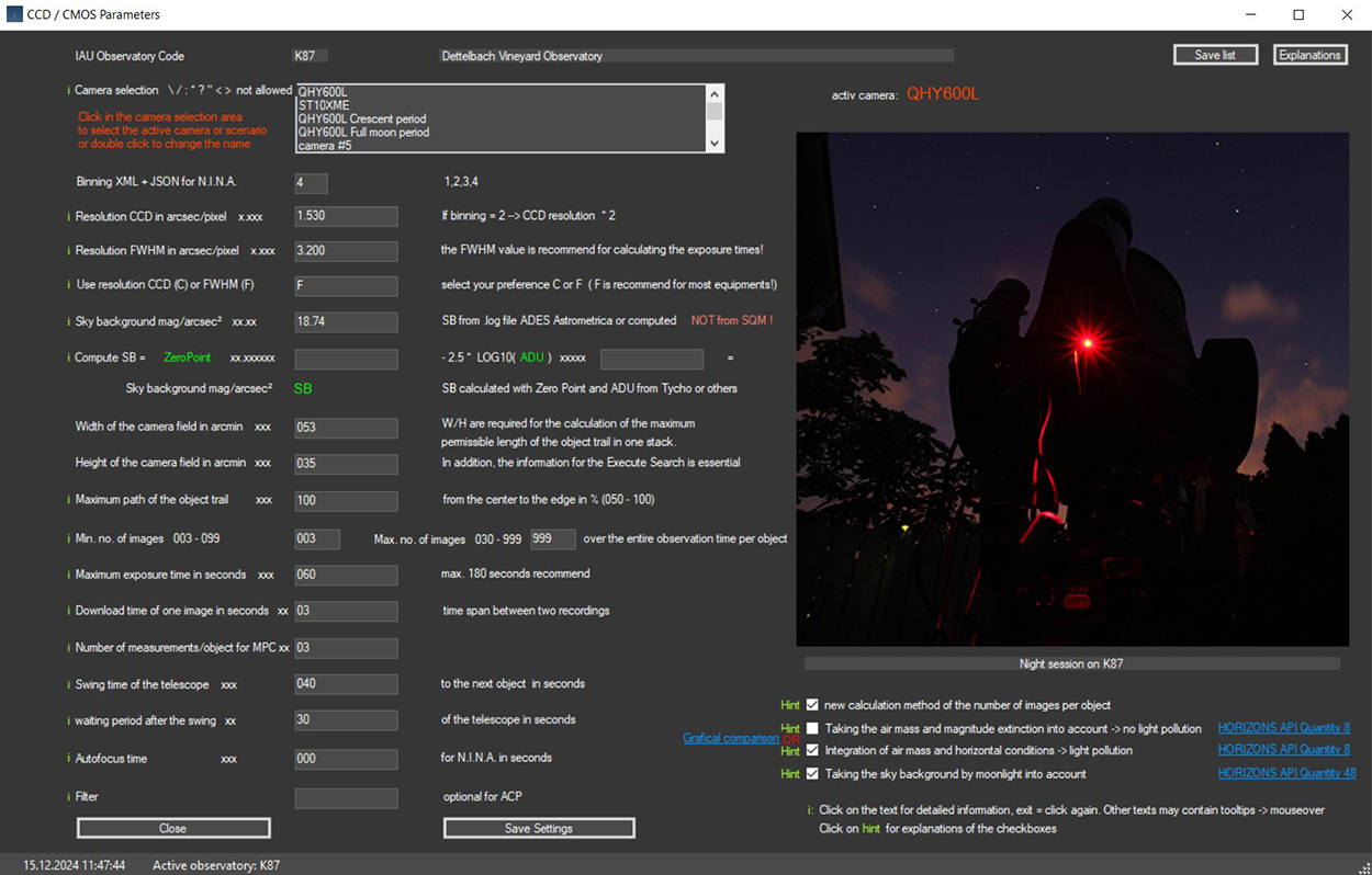
The active observatory is displayed.
The CCD / CMOS parameters can be entered individually for up to 30 cameras/equipments/scenarios per observatory.
The Execute Planning parameters for the selected camera are saved and reloaded
when the camera is reused.
This means you can now create up to 30 different scenarios in the CCD/CMOS
settings and use them in Execute Planning.
Example: Full moon settings with scenario QHY600L Full Moon period. There are no
limits to the various scenarios, except for the maximum limit of 30.
By clicking in the selection
menu, the camera settings are displayed and can be adjusted.
At the same time, the active camera used in Execute Planning or Execute Search
is determined by clicking on it.
The active camera is displayed in the relevant
windows.
Binning is required for the XML and JSON transaction files for
N.I.N.A.'s advanced sequencer of Stefan Berg or
output for ACP or .csv.
Always use the camera's highest binning value to achieve the greatest depth of
field. The binning value should be based on the FWHM.
Resolution CCD in arcsec/pixel:
Enter the resolution of the CCD chip here in arcseconds/pixel. For example, if
you are observing with 2 or 3 binning,
multiply the camera's basic resolution value by 2 or 3 and enter this value
here.
The FWHM is a frequently discussed value among observers. Everyone wants to
highlight the particularly good view of their location.
But let's just be realistic when entering this value. A good starting point is
to specify the seeing value in the Astrometrica .log files or in the display in
Tycho.
To determine the best exposure time for each object,
NEO Planner requires a FWHM value that allows precise measurement based on the
movement of the objects.
Therefore, it is best to enter a value that is close to a mean FWHM that
corresponds to the location in the past.
In this way, NEO Planner can largely ensure that an object is not exposed too
short or too long for a single position measurement.
Use resolution CCD (C) or FWHM (F):
The choice of which
kind of resolution you use
for calculating the exposure time is up to you and your
experience with your equipment.
Either enter C for CCD resolution or F for the seeing value FWHM.
The formula for calculating the exposure time of an object is:
exposure time (sec) = best FWHM (or
Resolution CCD) / velocity in s/min * 60
whereby the
maximum exposure time is not exceeded.
The exposure time is calculated and used
to the nearest tenth of a second, and it is, as can easily be seen,
dependent solely on the resolution of the CCD camera or the measured best FWHM
and the relative speed of the object
and not primarily on the aperture or the type of your
telescope.
For amateur
telescopes, the use of the FWHM value is generally sufficient,
because otherwise exposure times that are too short would make it more difficult to
find weak objects in the stacked images.
My former programs, which did the planning for the objects, related to my equipment
alone.
The particular challenge was therefore to calculate the correct number of images
for a single stack for other equipment as well.
After a few days of thinking, I got the idea to include the value of the sky
background in the calculation.
Because the combination of local conditions, CCD sensitivity and telescope aperture ultimately
results in the achieved sky background value
represented in the .log files
of ADES Astrometrica.
The sky background in mag/arcsec2 is now used
as an individual quality value for calculating the number of images required for
a single stack.
In fact, this value is the most important during planning.
Equipment calibration: Technique of calculating the sky background with
ADES Astrometrica:
Creation of some well-focused and calibrated light images (bias, dark, flat)
with an exposure time of 10 seconds and an altitude of approx. 55 degree.
which are won on moonless nights around the meridian.
Avoid bright stars in and around the FOV and regions of the Milky Way. It
doesn't matter using the best sky for the measurements, rather average nights.
Each of the images is measured with Astrometrica and the usual settings and set
the value 3 in the Aperture Radius.
After the data reduction, click on a star-free field and astrometry.
For the "Object verification" select any proposed asteroid and confirm (Accept).
Then select "View Log File" via the File tab and search for "Sky Background".
Make a note of this value.
If you like, calculate the sky background average from the images obtained from different
nights.
This average value is then entered in the settings.
The calculation of the sky background with the above method determines a good
comparison value
for all possible combinations of CCD cameras and telescopes
of all sizes and types in relation to the reference value of the sky background
I gained with my equipment under the mentioned conditions.
Astrometrica
or Tycho may show an SB value
that is too high or too low for images obtained with CMOS chips.
The calibration value of NEO
Planner refers to CCD chips and therefore you have to enter a lower
or higher value in the
settings in this case.
Therefore you have to approach the value through experiments.
Observe the
sum of exposures per group
calculated by the NEO planner and adjust the sky background value in the
settings,
if the sum of exposures
per stack (group) seem too low
or too high to you. Then lower
or higher the sky background value.
Sky Background:
Compute SB: Technique of calculating the sky background with Tycho:
Attention:
Users report that the NEO Planner Sky
Background value determined using Tycho is too low.
I therefore recommend not using the method listed below to determine this value.
There are two solutions:
1. Determine the value using ADES
Astrometrica, which is how I obtained it for my station.
2. Use a manually entered value around 18.5, which roughly corresponds to my
value.
You can then increase or decrease this value depending on
your experience with the quality of your own measurements.
For Tycho users, the sky
background can be calculated using two values.
On the one hand, the zero point of a recording is
required, and on the other hand, the ADC value of a
star-free area of the image is required.
The technique is initially similar to the Astrometrica method:
Creation of some well-focused and calibrated light images (bias, dark, flat)
with an exposure time of 10 seconds and an altitude of approx. 55 degree.
which are won on moonless nights around the meridian.
Avoid bright stars in and around the FOV and regions of the Milky Way. It
doesn't matter using the best sky for the measurements, rather average nights.
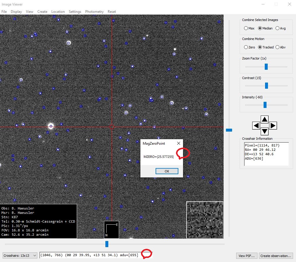
Then do the following in Tycho:
Load the 10 second image(s) from the Image Manager and List tab.
Align and plate solve the calibrated images over the "Action" tab. Then push
there "View Images". On the Image Viewer "File" tab run "Load Star Catalog".
Then push the "Photometry" tab and compute MZERO. Record this value as the
zero point.
Then move the cursor to a star-free place in the image.
Note the ADU
value, which is displayed at the bottom in the Image Viewer.
Repeat this method with other images and form an ADU mean.
The example shown is not the 10 seconds reference image from K87.
The sky background is then calculated using the following
formula: SB = Zero Point - 2.5 * LOG10 (ADU)
Reference of the formula: Rainer Kracht, Astronomer:
Die
Messung der Himmelshelligkeit. (rkracht.de)
Old calculation method of the number of images per stack, conceived by Bernhard H�usler:
Let's go into the depth of the calculation.
The reference values come from an image with a sky background
value of 18.74 mag = RefSB on K87.
An asteroid was photographed with 16.6 arc seconds / min =
Refvelo and a brightness of 19.4 mag = Refmag.
50 stacked images = Refimg
were necessary so that the asteroid could be measured reliably.
I use exactly these reference values on K87 to calculate the number of necessary
images for all objects for my equipment.
Some basics first:
The difference between two integer magnitudes means a reduction
or increase in brightness of 2.512 times
The formula for exponential growth or decay is then 2.512difference
First step for calculation the number of images for one stack according to the brightness in mag of the object:
dmag (Difference) = Refmag - Vmag(Object)
The number of images increases or decreases exponentially by 2.512 dmag
Number of images (1) = Numimg1 according to the reference value of Refimg:
Exponential factor (with negative value of dmag = growth)
Exponential divisor (with positive value of dmag = decay)
Growth: Numimg1 = Refimg * 2.512
dmag * -1
Decay: Numimg1 = Refimg / 2.512
dmag
Second step for calculation the number of images for one stack according to the velocity of the object:
Number of images (2) = Numimg2 according to the reference value of Refvelo:
Numimg2 = Numimg1 * Objvelo / Refvelo
I use exactly rounded Numimg2 on K87 for the number of images for a single stack.
Third step for calculation the number of images for one stack according to the sky background for any equipment:
SBdiff (Difference) = RefSB - settingsSB
Exponential divisor (with negative value of SBdiff = growth) !
Exponential factor (with positive value of SBdiff = decay)
!
Growth: Numimg3 = Numimg2 / 2.512
SBdiff * -1
Decay: Numimg3 = Numimg2 *2.512
SBdiff
New calculation method of the number of images per stack, conceived by Heiko Duin, L65 Bredenkamp Observatory, Bremen:
Switch in the CCD Settings to use a new calculation method for the number of
exposures per object:
The number of images with longer maximum exposure times (e.g. 120
or 180 seconds) and shorter maximum exposure times (e.g. 30 or 15 seconds)
are now calculated correctly. Compared to the previous method, this shortens the
number of images with longer exposure time
and increases the number of shots of slow objects and short exposure time.
Reference values of K87:
href_magex = 0.313 Reference value airmass extinction
href_exposures = 50 Reference value Number of images
href_reso = 3.2 Reference value Resolution FWHM
href_velo = 16.6 Reference value s/min
href_sb = 18.74 Reference value Sky Background SB of NEO Planner
href_mag = 19.4 Reference value Vmag object
href_beltotal = 500 Reference value Total exposure time in seconds for one
measurement
Station values:
sref_reso = resFWHM Station value Resolution FWHM
sref_sb = skybackground Station value Sky Background SB of NEO Planner
sref_maxexp = maxexp Station value maximum exposure time in seconds
Formula Visual Basic:
step1 = sref_reso / velocity(obj) * 60
step2a = href_mag - Vmag(obj)
step2b = href_sb - sref_sb
step2c = step2a - step2b
step3 = 1 / (2.512 ^ step2c)
step4 = href_beltotal * step3
If step1 > sref_maxexp Then
step5 = sref_maxexp
Else
step5 = step1
End If
step6 = CInt(Math.Floor(step4 / step5)) + 1
total number of exposures = step6 * number of
groups
Heiko's method is more elegant and mathematically precise than my old method.
The minimum number of images per stack is 1.
Both methods make it possible to calculate the necessary image sequences
independently of the equipment.
I would like to add one important hint. Objects of the
solar system, regardless of their type,
have different albedos due to their
chemical and physical properties.
So it is perfectly normal that a carbon-rich asteroid is harder to astrometry
than a ferrous one.
The same is true for highly condensed comas in comets as compared to less
strongly condensed comas.
However, NEO Planner cannot know the albedo of the individual objects.
Therefore
everyone has to expect that the observation can go wrong due to
too few images in the stack.
For years I have been observing NEO and comets with my formula and have achieved
useful results.
Both the reference data and the formulas
therefore have a certain practical value, and do not represent scientific
perfection
Taking airmass and magnitude extinction into account (scientifically, all objects)
Useful when humidity is low and/or there is little or no light brightening the horizon.
When the checkbox is activated, the relative airmass of the location is taken into
account
when calculating the number of images per group/stack.
The altitude of the object at the time of observation is used.
The consideration of airmass and moon-sky background is only calculated at
altitudes above the minimum value in the Common
Restrictions.
The values used to calculate the airmass come from the JPL HORIZONS API, here
is the description:
_RELATIVE_ optical airmass and magnitude extinction:
Airmass is the ratio of the absolute optical airmass at the targets refracted
elevation angle with the absolute optical airmass at zenith.
Also output is the estimated visual magnitude extinction due to atmosphere, as
seen by the observer. (end of description)
Source: Description
HORIZONS API
Quantity 8
The formula for calculating the airmass is (source:
Heiko
Duin, L65 Bredenkamp Observatory, Bremen):
mag_ex = estimated visual magnitude extinction
a-mass = _RELATIVE_ optical airmass
extf = mag_ex / a-mass
factor = 10 ^ ((a-mass - 1) * extf / 2.512)
The number of images calculated by NEO Planner is now multiplied by the factor.
Airmass is used together with the Sky brightness due to moonlight value if the
checkboxes of both values are activated.
Both values are gradually integrated, otherwise only the activated value or
none.
The airmass is multiplied by the number of calculated
images per group/stack using floating point numbers.
Thus, the total number of images is increased during planning.
The calculation of the number of images including airmass and lunar sky
brightness is carried out using floating point numbers.
This means that it is not always possible to derive the number per group/stack
in Revise. Please take this fact into account!
The more images per group are originally required, the more accurate the result
will be.
Integration of airmass and horizontal conditions (practically, all objects)
Useful when humidity is high and/or there is light brightening the horizon.
When the checkbox is activated, the relative airmass of the location is taken into
account
when calculating the number of images per group/stack.
The altitude of the object at the time of observation is used.
The consideration of airmass and moon-sky background is only calculated at
altitudes above the minimum value in the Common
Restrictions.
However, the value determined for the airmass does not take the local
conditions into account.
Humidity and increasing light pollution near the horizon can negatively affect
observations of objects at larger zenith angles.
So, the value _RELATIVE_ optical airmass from the JPL HORIZONS API is best suited
for this fact:
Airmass is the ratio of the absolute optical airmass at the targets refracted
elevation angle with the absolute optical airmass at zenith. Source: Description
HORIZONS API
Quantity 8
The number of images calculated by NEO Planner is
now
multiplied by a-mass.
Airmass is used together with the Sky brightness due to moonlight value if the
checkboxes of both values are activated.
Both values are gradually integrated, otherwise only the activated value or
none.
The airmass value is multiplied by the number of calculated
images per group/stack using floating point numbers.
Thus, the total number of images is increased during planning.
The calculation of the number of images including airmass and lunar sky
brightness is carried out using floating point numbers.
This means that it is not always possible to derive the number per group/stack
in Revise. Please take this fact into account!
The more images per group are originally required, the more accurate the result
will be.
Difference and connection between both methods:
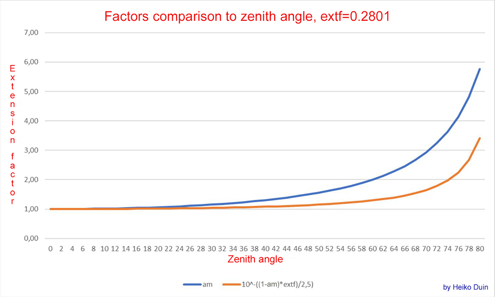
Source: Heiko Duin, Bremen
Illustration of the difference between the two airmass methods.
The blue line shows the course of the expansion factor when the horizon
brightens at the observatory (practically),
the orange line shows the extension factor without horizon brightening (scientifically).
The extf-0.2801 value corresponds to an
extf at sea level. (see
Reference, Table 1a)
Explanations about Airmass and Extinction (by Heiko Duin):
Extinction is given as a coefficient per airmass in magnitudes,
so the extinction for an object with an angle z from the zenith is:
airmass * ext_factor, where airmass depends on z.
Extinction depends on many factors, e.g. humidity and altitude above sea level
and is therefore difficult to calculate directly for a given location and
weather conditions.
Fortunately, the HORIZONS interface also provides Airmass and Extinction in the
ephemerides (a_mass and mag_ex).
These are determined according to the Obs code, so we don't have to worry about
altitude above sea level.
From the HORIZONS data you can easily determine the extinction coefficient with
extf = mag_ex / a_mass (in mag).
The reference measurement from K87 resulted in a specific magnitude for an
object.
However, in photometry the measured value is calculated to be �above the
atmosphere�.
This means that (at least) one airmass was already taken into account when
measuring on K87.
Therefore, only (Airmass � 1) needs to be taken into account when calculating
the extension factor.
If you now convert mag into flux and put everything together, you get the
extension factor vlf:
vlf = 10^((am-1)*extf/2.5) = 10^-((1-am)*extf/2.5)
am = airmass
This corresponds to the orange curve in the diagram, while the blue curve
indicates the associated airmass.
The extinction coefficient value of 0.28 comes from Green (1992) (http://www.icq.eps.harvard.edu/ICQExtinct.html)
and is an average extinction coefficient for a site on normal Zero level.
Light pollution does not affect extinction, at least I haven't found any
evidence of it.
The extension due to light pollution is controlled by the background value (in
mag per square arcsecond).
Reference: Green D. W. E. Correcting for Atmospheric Extinction, July 1992
Taking the Lunar Sky Brightness into account (all objects)
When the checkbox is activated, the Sky brightness due to moonlight and the
position of the object in the sky
is taken into account when calculating the number of images per group/stack.
The value is determined from the JPL HORIZONS API, here is the description:
Sky brightness due to moonlight scattering by Earth's atmosphere at the target's
position in the sky.
Output only for topocentric Earth observers when both the Moon and target are
above
the local horizon and the Sun is in astronomical twilight (or further) below the
horizon.
Galactic brightness, local sky light-pollution and weather are NOT considered.
Lunar opposition surge is considered. The value returned is accurate under ideal
conditions
at the approximately 8-23% level, so is a useful but not definitive value.
Source: Description
HORIZONS API
Quantity 48
Sky brightness due to moonlight is used together with the airmass value if the
checkboxes of both values are activated.
Both values are gradually integrated, otherwise only the activated value or
none.
The lunar sky brightness is multiplied by the number of
calculated images per group/stack using floating point
numbers.
Thus, the total number of images is increased during planning.
The calculation of the number of images including airmass and lunar sky
brightness is carried out using floating point numbers.
This means that it is not always possible to derive the number per group/stack
in Revise. Please take this fact into account!
The more images per group are originally required, the more accurate the result
will be.
If activated, it is no longer necessary to increase the groups in Revise in disturbing moonlight.
If desired, by entering the field of view (FoV) of the CCD or
CMOS chip, the number of groups (stacks) can be automatically recalculated
with a simultaneous increase in the recording positions for each planning, if
the object threatens to leave the FoV during the exposure series.
The path length of an object through the FoV is calculated based on the movement
of the object in arcsec/min, its position angle,
the exposure times including download load times and the number of exposures per
series.
Allocation of positions per object:
Normal planning takes place first, then the excesses of the FoV are determined
for objects,
which leads to a recalculation of the planning in terms of time and
content.
The procedure is as follows:
First, it is checked whether the movement of the object is greater than the
maximum path according to the number of shots
and the groups set (3 or 4 or 11,
etc.).
If not, the position remains as it is.
If so, the position needs to be adjusted. There are several options for reacting
to exceeding the maximum path length.
In order to simplify the complexity, the number of groups is reduced to 1 in
this case and the positions are supplemented
by the number of groups originally
required.
This means that, for example, a series of recordings per object is divided from
the original 4 groups to 4 x 1 group.
In the revise, there are then, for example, four positions for such objects
instead of one, including a repositioning
and complete recalculation of all
parameters for NINA.
However, new groups only if the CCD FOV is filled in the settings and the number
of groups is > 1.
In addition, width and height are essential for the Execute Mosaic Search.
Width of the camera field in arcmin:
Total width of the FoV
Height of the camera field in arcmin:
Total height of the FoV.
Maximum path of the object trail:
Maximum path that an object is allowed to travel from the center of the image to the edge during a series of exposures.
The path length of the individual series is determined
based on the <Center Pos.> checkbox in the Execute Planning Window.
If the checkbox is not checked, the path length is at the center of the image;
if the checkbox is checked, the path length is from the object's starting
position.
The maximum path of 100% is automatically determined by
the FoV and can be reduced by entering a percentage.
90% means that the maximum path length of the FoV is shortened by 10%, 80% means
that the maximum path length is shortened by 20%.
This ensures that the object is not recorded up to the edge.
If it is found in a series of recordings that the maximum permissible path is
exceeded,
the planner splits the observation of the object into several
positions.
At the same time, the number of groups (stacks) per position is reduced to 01.
For each object position, R.A. and decl. and all exposure values and observation
times are recalculated.
The division into several positions can then be adjusted manually in the revise
window.
You can delete too many positions there or adjust the number of groups (stacks)
as you like.
In the case of planning, the maximum path length is always recalculated if the
number of groups is > 01.
Calculation of recordings:
At least three images are required for the required measurements per
object and night.
As a rule, this value of 03 should therefore be set here. This applies to all
surveying programs such as Astrometrica or Tycho etc.
However, there are at least two cases where the minimum number of images should
be increased.
1th For observations around the full moon time +/- 3-4 days you
should at least double the value.
This is not
necessary if you choose to take the lunar sky background into account
when planning.
2nd When using Tycho's Synthetic tracker for astrometry.
This value does not play a role when
calculating the number of total images,
but it does play a role in determining
the number of images in the final planning in the Revice Window.
NEO Planner ensures that at least the
specified number of images are used in the planning list,
regardless of whether they are
actually needed for a measurement or not.
Maximum number of images:
If the default maximum total number of images per object of 999 seems too large
for practical use, you can limit the maximum number
of total images per object. This can be the case, for example, because of long
loading times for images from remote telescopes.
In Revise, the number of
images is displayed in red if it is less than the
calculated number of images per group * number of groups.
In this case, you should proceed with caution when measuring the objects.
Maximum exposure time in seconds:
After calculating the exposure
time, a check is made to determine whether the maximum exposure time set here
has been exceeded.
If so, this time is used.
You can find information about the exposure time here.
Download time of one image in seconds:
The download time for each individual image is a very important value.
Especially with fast objects with short exposure times and many images per
stack,
the download time plays an important role in calculating the total
exposure time of an object.
This value should be specified to the second.
Number of measurements (stacks) / object:
The group value
basically means how many measurements for each single
object should be sent to the MPC.
After planning, you can increase this value for each
object in the Revise Window if you want.
This sensitive value is based on the
rules of the MPC, which determine the quality of the measurements.
In order to meet the requirements of independent stacks and at least
two or three measurements per
object,
this parameter ensures that enough recordings per object are always suggested in
the planning.
Three measurements per object should be mandatory. It can happen
that the MPC rejects two measurements per object.
For a measurement that complies with the rules, NEO Planner calculates, on the
one hand,
the number of recordings per individual stack using the
sky background,
and on the other hand, the number of groups ensures that
enough stacks are available for the measurement.
With bright objects or with a deep sky background, individual
unstacked images can of course also be measured if the quality is
available.
NEO Planner calculates all the necessary planning data for the measurement of
NEO
and comets according to the individual settings of each observer.
However, the suggested values are not compulsory and it is up to the observer to
evaluate the images.
This parameter defines the time the telescope needs to move to the next
object and to lock in.
This can also be the time in seconds that elapses on average for
manual work between observing two objects.
Waiting period after the swing:
Use this time span in seconds to give the guider enough time to activate himself after panning the telescope.
If in the settings of N.I.N.A. autofocus parameters are activated, you can enter the corresponding period of time in seconds here.
Optional entry of a filter
name for ACP
The sky background has to be re-measured for each filter.
A separate camera should be entered for each filter